Contents
Chapter 5 · NetworkPractice

LEARN WITH HARU

Video Lesson တွေက Haru အတန်းသားတွေအတွက်ပါ

Haru ရဲ့ ITPEC FE Full Course မှာ ယခု သင်ခန်းစာတွေကို တစ်ခုချင်း တစ်ကြောင်းချင်း အသေးစိတ်ရှင််ရှင်းပြထားပါတယ်

အခြေခံ မရှိတဲ့ ကျောင်းသားများစွာဟာလည်း ဒီ Course နဲ့ ပဲ အောင်မြင်ကုန်ကြပါပြီ

အတန်းမအပ်သေးပဲ Haru ဆီမှာ အစမ်းသင်ကြည့်ချင်ပါသလား?

သင်တန်းသားတွေရဲ့ စကားသံများ

သင်တန်းသားတွေရဲ့ စကားသံများ

Highlighted text? Practice this concept. Highlighted passages and figures open related questions.

Practice related questions (4)Progress & bookmarks

Current section

1-3-3 Error Control Method

p. 295

Practice this section 4 linked exam questions with default filters

Progress

Not marked complete

Related questions in this lesson 5

Even and vertical parity1CRC polynomial division1Huffman source coding1ECC and memory error correction1Hamming distance1
Progress and bookmarks

p. 295

1-3-3 Error Control Method

Error control refers to controlling the bit errors that occur on the communication channel when data is transmitted. Shannon recommends the two encodings that are described below as

p. 296

the coding theory for improving reliability, efficiency, and safety in the course of information transmission.

(1) Source coding

Source coding refers to encoding (.i.e., data compression) of the information source to reduce the amount of transmission data (i.e., number of bits). This is a concept according to which, if the bit error rate of the communication channel, etc. is a fixed value, the lower the number of transmission bits the more difficult it is for an error to occur. There are two typical methods of source coding as described below.
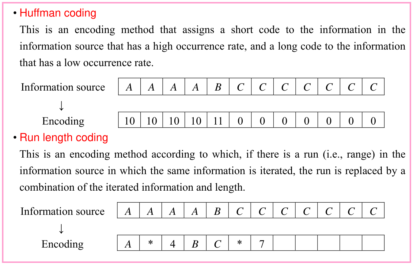
Original Error Control Method source table or explanation box, preserving its complete original arrangement, labels and values. Source text: • Huffman coding This is an encoding method that assigns a short code to the information in the information source that has a high occurrence rate, and a long code to the information that has a low occurrence rate. Information source A A A A B C C C C C C C ↓ Encoding 10 10 10 10 11 0 0 0 0 0 0 0 • Run length coding This is an encoding method according to which, if there is a run (i.e., range) in the information source in which the same information is iterated, the run is replaced by a combination of the iterated information and length. Information source A A A A B C C C C C C C ↓ Encoding A * 4 B C * 7
p. 296 · Enlarge
Huffman source coding · 1 practice questions

(2) Channel Coding

Channel coding refers to appending a single or multiple redundant bits that are different from the information source to perform encoding. This is a concept that can detect an error that has occurred in the communication channel and can correct the error by using the appended redundant bit. It is generally called the error detection and correction method. The typical kinds of the error detection and correction method are as described below.

p. 297
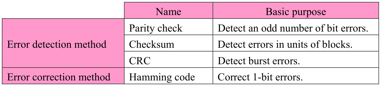
Original Error Control Method source table or explanation box, preserving its complete original arrangement, labels and values. Source text: Name Basic purpose Parity check Detect an odd number of bit errors. Error detection method Checksum Detect errors in units of blocks. CRC Detect burst errors. Error correction method Hamming code Correct 1-bit errors.
p. 297 · Enlarge

(1) Parity check This is a method that detects an error by appending a redundant bit (i.e., parity bit) for checking to the bit string to be transmitted. This method can be classified into several techniques as shown below depending on the regularity of the redundant bit and the target to which the redundant bit is to be appended.
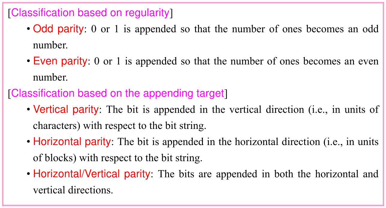
Original Error Control Method source table or explanation box, preserving its complete original arrangement, labels and values. Source text: [Classification based on regularity] • Odd parity: 0 or 1 is appended so that the number of ones becomes an odd number. • Even parity: 0 or 1 is appended so that the number of ones becomes an even number. [Classification based on the appending target] • Vertical parity: The bit is appended in the vertical direction (i.e., in units of characters) with respect to the bit string. • Horizontal parity: The bit is appended in the horizontal direction (i.e., in units of blocks) with respect to the bit string. • Horizontal/Vertical parity: The bits are appended in both the horizontal and vertical directions.
p. 297 · Enlarge
Even and vertical parity · 1 practice questions
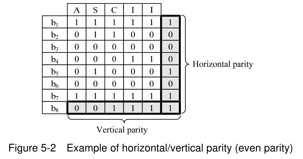
Two-dimensional even-parity matrix, with character columns, bit rows and horizontal and vertical parity. Source text: Figure 5-2 Example of horizontal/vertical parity (even parity)
p. 297 · Enlarge

In the parity check, while an odd number of bit errors can be detected, an even number of bit errors cannot be detected. By using the horizontal/vertical parity check technique, it is

p. 298

possible to identify one bit error and its position (i.e., intersection point of the column and row in which the error has occurred). However, since the error may occur in several bits, the error correction function is generally not made available in the parity check.

(2) Checksum This is a method that detects an error by appending redundant bits (e.g., a total value) that is determined through a simple calculation in units of blocks.
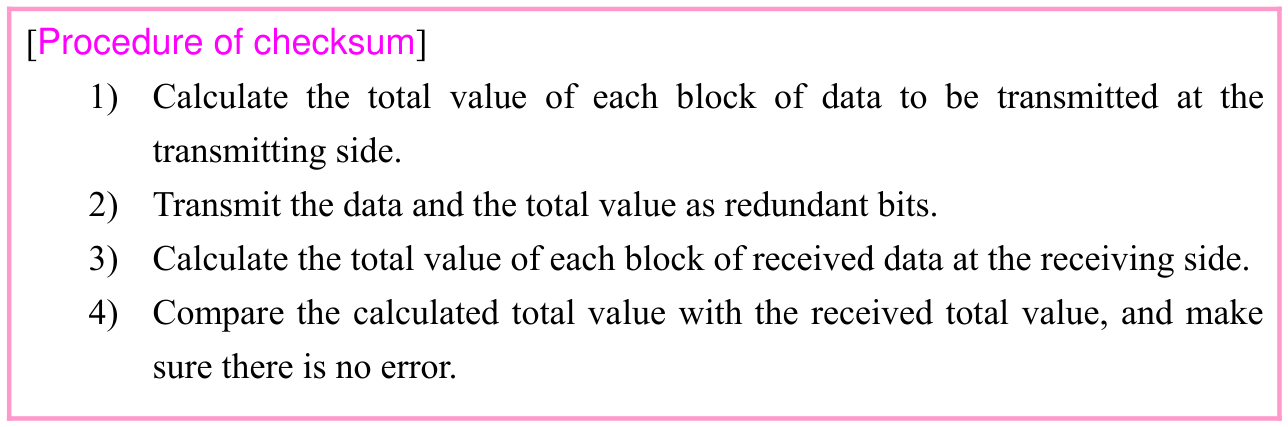
Original Error Control Method source table or explanation box, preserving its complete original arrangement, labels and values. Source text: [Procedure of checksum] 1) Calculate the total value of each block of data to be transmitted at the transmitting side. 2) Transmit the data and the total value as redundant bits. 3) Calculate the total value of each block of received data at the receiving side. 4) Compare the calculated total value with the received total value, and make sure there is no error.
p. 298 · Enlarge

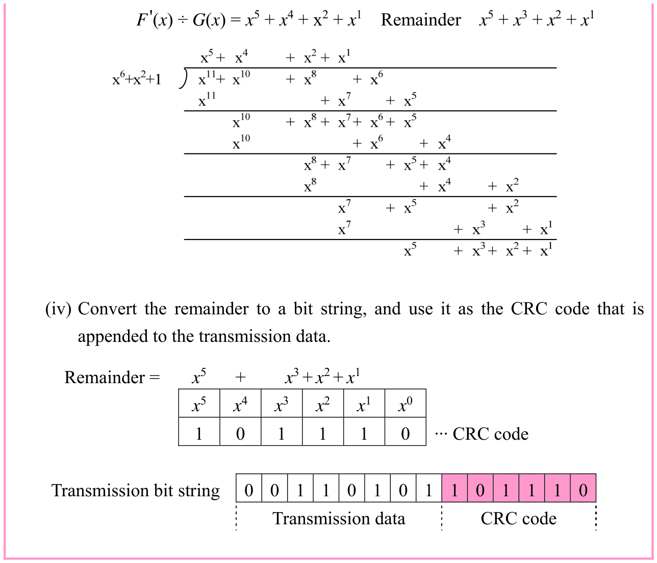
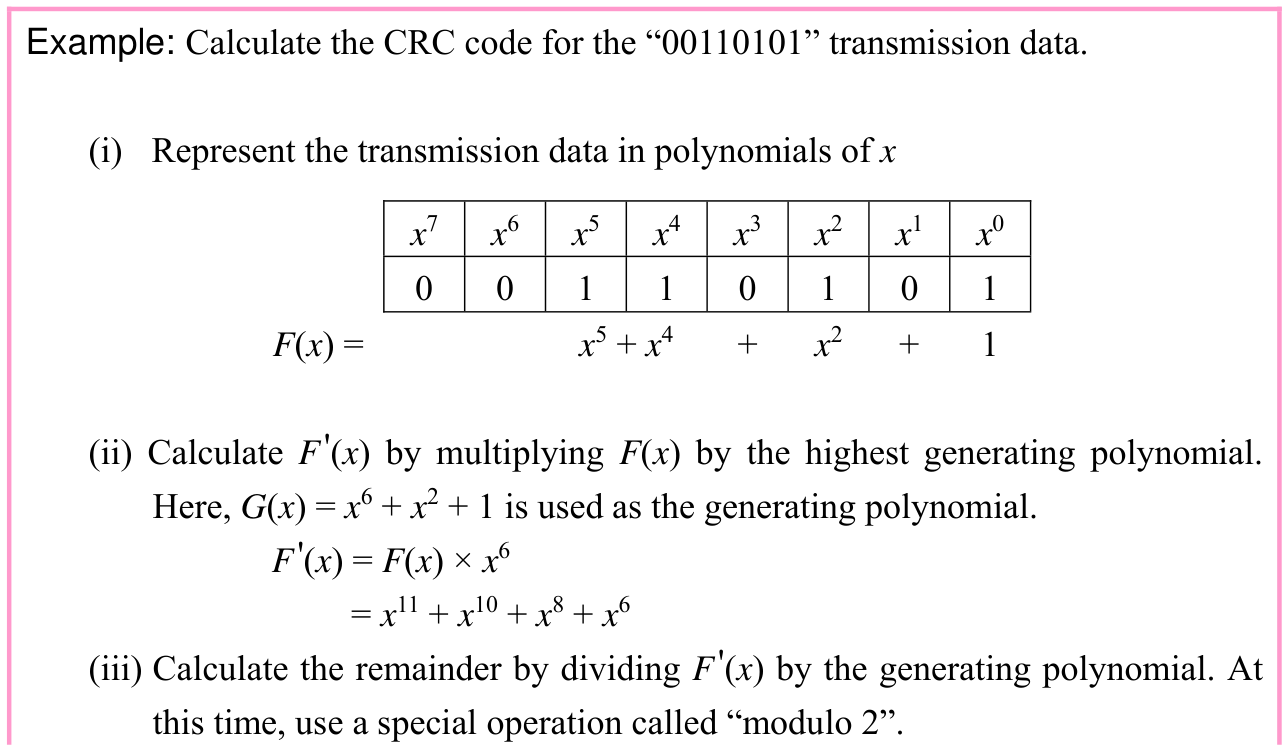
(3) CRC (Cyclic Redundancy Check) This is a method in which transmission data is represented by a polynomial, the polynomial of the transmission data is divided by a predetermined generating polynomial, and then a checking code (CRC code) that is obtained by converting the remainder to a bit string is appended. At the receiving side, the reception data that is represented by a polynomial is divided by a generating polynomial, and the existence of an error is detected depending on the divisibility. This is a highly accurate error detection method by which continuous bit errors (i.e., burst error) can be detected. · 1 question

Original Error Control Method source table or explanation box, preserving its complete original arrangement, labels and values. Source text: Example: Calculate the CRC code for the “00110101” transmission data. (i) Represent the transmission data in polynomials of x x7 x6 x5 x4 x3 x2 x1 x0 0 0 1 1 0 1 0 1 F(x) = x5 + x4 + x2 + 1 (ii) Calculate F'(x) by multiplying F(x) by the highest generating polynomial. Here, G(x) = x6 + x2 + 1 is used as the generating polynomial. F'(x) = F(x) × x6 = x11 + x10 + x8 + x6 (iii) Calculate the remainder by dividing F'(x) by the generating polynomial. At this time, use a special operation called “modulo 2”.
p. 298 · Enlarge

p. 299

Original Error Control Method source table or explanation box, preserving its complete original arrangement, labels and values. Source text: F'(x) ÷ G(x) = x5 + x4 + x2 + x1 Remainder x5 + x3 + x2 + x1 (iv) Convert the remainder to a bit string, and use it as the CRC code that is appended to the transmission data. Remainder = x5 + x3 + x2 + x1 x5 x4 x3 x2 x1 x0 1 0 1 1 1 0 ··· CRC code Transmission bit string 0 0 1 1 0 1 0 1 1 0 1 1 1 0 Transmission data CRC code
p. 299 · Enlarge

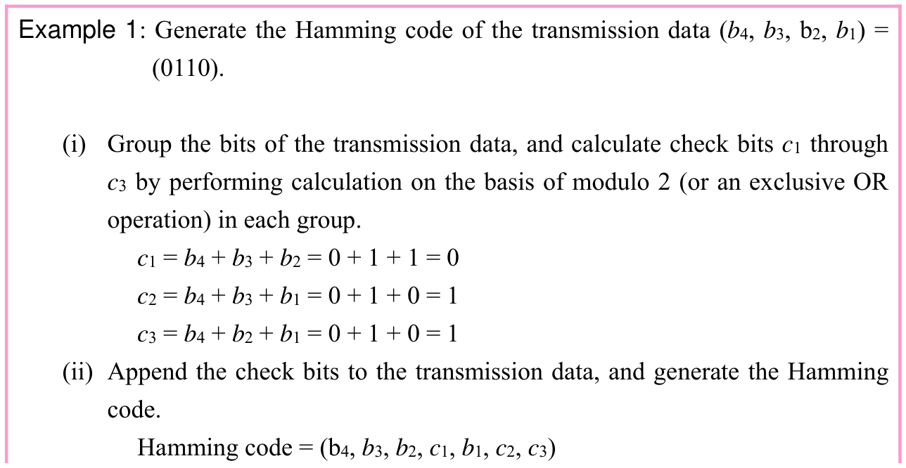
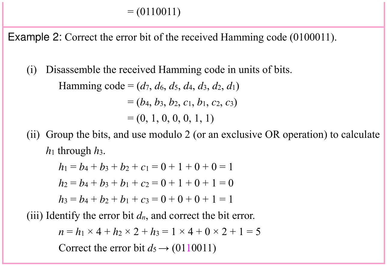
(4) Hamming code This is a method that enables the detection and correction of bit errors. A code like the Hamming code that has the purpose of correcting errors is called an ECC (Error Correcting Code). The ECC is also used for correcting errors in memory. · 1 question

Original Error Control Method source table or explanation box, preserving its complete original arrangement, labels and values. Source text: Example 1: Generate the Hamming code of the transmission data (b4, b3, b2, b1) = (0110). (i) Group the bits of the transmission data, and calculate check bits c1 through c3 by performing calculation on the basis of modulo 2 (or an exclusive OR operation) in each group. c1 = b4 + b3 + b2 = 0 + 1 + 1 = 0 c2 = b4 + b3 + b1 = 0 + 1 + 0 = 1 c3 = b4 + b2 + b1 = 0 + 1 + 0 = 1 (ii) Append the check bits to the transmission data, and generate the Hamming code. Hamming code = (b4, b3, b2, c1, b1, c2, c3)
p. 299 · Enlarge

p. 300

Original Error Control Method source table or explanation box, preserving its complete original arrangement, labels and values. Source text: = (0110011) Example 2: Correct the error bit of the received Hamming code (0100011). (i) Disassemble the received Hamming code in units of bits. Hamming code = (d7, d6, d5, d4, d3, d2, d1) = (b4, b3, b2, c1, b1, c2, c3) = (0, 1, 0, 0, 0, 1, 1) (ii) Group the bits, and use modulo 2 (or an exclusive OR operation) to calculate h1 through h3. h1 = b4 + b3 + b2 + c1 = 0 + 1 + 0 + 0 = 1 h2 = b4 + b3 + b1 + c2 = 0 + 1 + 0 + 1 = 0 h3 = b4 + b2 + b1 + c3 = 0 + 0 + 0 + 1 = 1 (iii) Identify the error bit dn, and correct the bit error. n = h1 × 4 + h2 × 2 + h3 = 1 × 4 + 0 × 2 + 1 = 5 Correct the error bit d5 → (0110011)
p. 300 · Enlarge

The number of bits that can be detected or corrected by the Hamming code is decided by the Hamming distance (i.e., the number of different elements (i.e., bits) in the information bits of the same bit length). · 1 question

  • • If the hamming distance is “m+1” or more, m bit errors can be detected.
  • • If the hamming distance is “2n+1” or more, n bit errors can be corrected.
    In the Hamming code that is created in example 1, three redundant bits are added to the four-bit data. Therefore, it is called the (7, 4) Hamming code. Since the Hamming distance becomes three or more, it is possible to correct one bit error and detect two bit errors.

Original chapter exercises

Original chapter exercises →

New FE Textbook Vol.1 · IT Fundamentals · First Edition, April 2015