Highlighted text? Practice this concept. Highlighted passages and figures open related questions.
Practice related questions (2)Progress & bookmarks
Current section
1-2-3 Software Detailed Design Process
p. 253
Progress
Not marked complete
Related questions in this lesson 2
STS module partitioning1Original STS partitioning diagrams1Module coupling order1Module independence and weak coupling1p. 253 · PDF 257
1-2-3 Software Detailed Design Process
The software detailed design process provides a design for the software that implements and can be verified against the software requirements and software architecture and is sufficiently detailed to permit coding and testing.
[Activities of software detailed design process] (i) Software detailed design (ii) Evaluation and review of software detailed design
(1) Software detailed design
Six tasks are executed in software detailed design.
(i) Detailed design of software components
Software components are refined into lower levels containing software units (i.e., a single unit, classes, and modules) that can be coded, compiled, and tested. It is confirmed that all software requirements are allocated from the software components to software units. This is documented in a software detailed design document (i.e., component detailed design document). (ii) Detailed design of software interfaces
A detailed design is to be developed and documented for the external interfaces of the software configuration items, the interfaces between the software components, and the interfaces between the software units. (iii) Detailed design for the databases
A detailed design for the database is to be developed and documented. (iv) Updating user documentation
User documentation is to be updated as necessary. (v) Definition of test requirements for software units
Test requirements and the schedule for testing software units are to be defined and documented. The scope, test plans, test procedures, and others of software unit test are to be defined, and a software unit test specifications document is to be developed. It is desirable that the test requirements include the stress test of the software unit at the limits of its requirements. (vi) Updating of test requirements for software integration
The test requirements and the schedule for software integration are to be updated.
p. 254 · PDF 258
In software detailed design, software components (i.e., programs) are partitioned into the units of coding called software units.
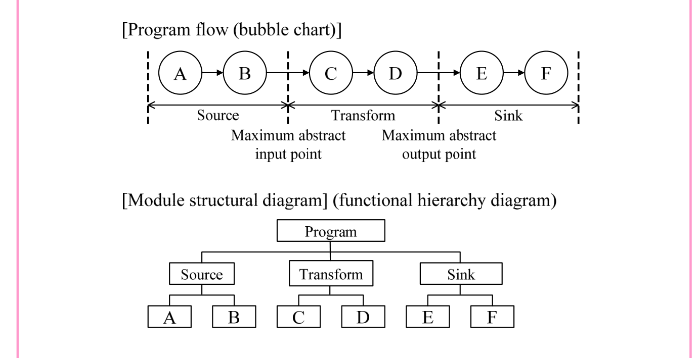
Task (i) described above is also called module design, because software component is partitioned into modules, which are the units of development (i.e., coding). In the module partitioning that is conducted during module design, structured design using the concept of structuring is used. For the module partitioning that is used in structured design, there are methods that focus on the flow of processing (or data). In general procedures, higher-level module partitioning is first performed by using STS partitioning, after which lower-level modules are partitioned by using transaction partitioning. After this, the modules are verified, and common functional partitioning is performed.
[Module partitioning techniques focused on the flow of processing (or data)]

Source visual description
Program flow (bubble chart): A points to B, B to C, C to D, D to E, and E to F. Source contains A and B; Transform contains C and D; Sink contains E and F. Dashed vertical boundaries mark the maximum abstract input point between B and C and the maximum abstract output point between D and E. Beneath, the Module structural diagram (functional hierarchy diagram) has Program above Source, Transform and Sink; Source has children A and B, Transform C and D, and Sink E and F.
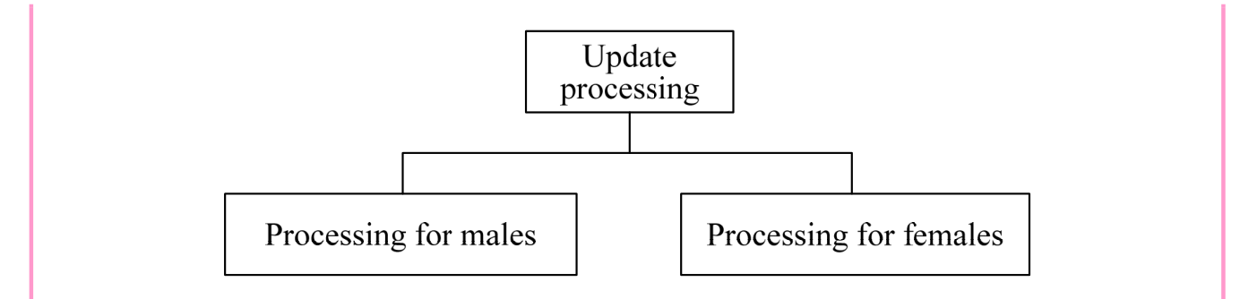
- • TR partitioning (Transaction partitioning)
This is a technique that partitions each process as a module when processing differs according to type of data. As an example, when processing procedures differ for males and females in file updating, partitioning can be performed as follows:
p. 255 · PDF 259

Source visual description
Update processing has two child boxes: Processing for males and Processing for females.
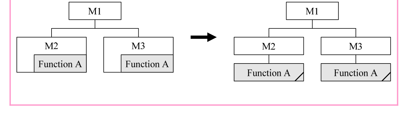
- • Common functional partitioning
When there are functions that are common to multiple partitioned modules, this technique partitions these functions into a single independent module.

Source visual description
The left hierarchy has M1 above M2 and M3; each lower module contains Function A. A rightward arrow leads to a hierarchy with M1 above M2 and M3 and one shared Function A box beneath them. Both lower modules connect to the common Function A; the source shows its folded-corner mark.
In addition to methods focused on the flow of processing (or data), there are also methods of module partitioning that focus on data structure.
[Module partitioning techniques focused on data structure]
- • Jackson method
This is a technique that analyzes input data and output data, and partitions modules according to the output data structure. In the Jackson method, both data structures and program structure are represented as three basic structures (sequence, selection, and iteration). - • Warnier method
This is a technique that uses the set theory to analyze input data structures from the perspective of when and how many times to perform processing.
Modules partitioned in this way must be evaluated for independence. Module strength and module coupling are used as metrics for evaluation.
p. 256 · PDF 260
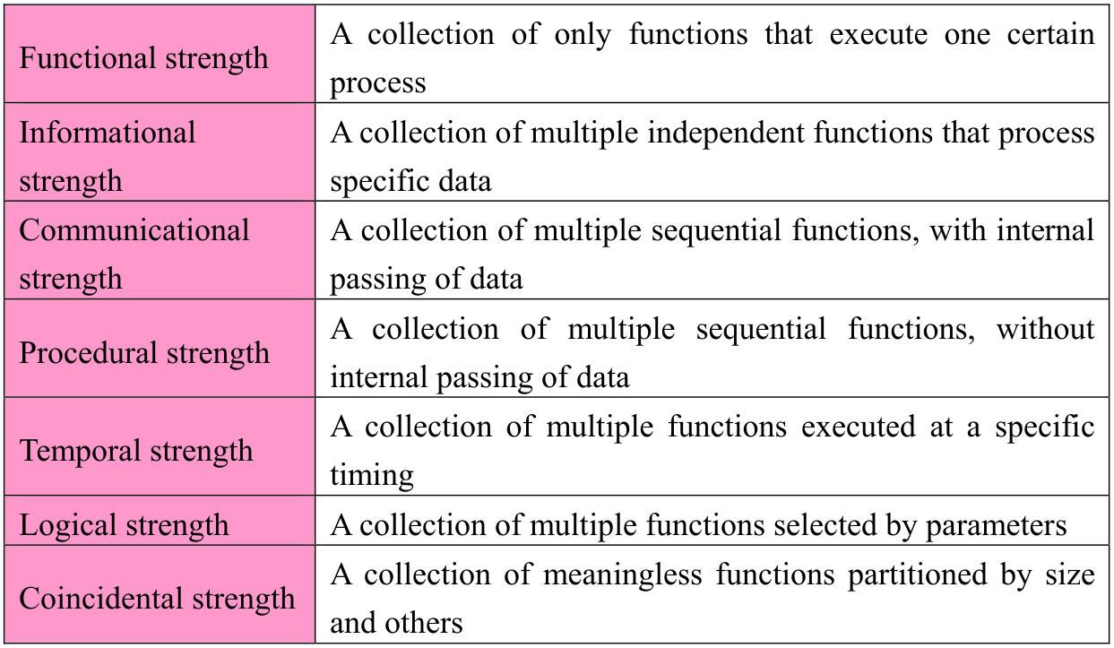
- • Module strength
This metric represents the associations of functions within the module. A better module has a higher strength. When modules are arranged in order of higher module strength, the result is as follows:
| Functional strength | A collection of only functions that execute one certain process |
|---|---|
| Informational strength | A collection of multiple independent functions that process specific data |
| Communicational strength | A collection of multiple sequential functions, with internal passing of data |
| Procedural strength | A collection of multiple sequential functions, without internal passing of data |
| Temporal strength | A collection of multiple functions executed at a specific timing |
| Logical strength | A collection of multiple functions selected by parameters |
| Coincidental strength | A collection of meaningless functions partitioned by size and others |

| Data coupling | Passes only parameters that do not affect control |
|---|---|
| Stamp coupling | Passes the data structure itself |
| Control coupling | Passes parameters that affect control |
| External coupling | Externally declares and shares only necessary data |
| Common coupling | Externally declares and shares data including unnecessary data |
| Content coupling | Directly looks up data in other modules |

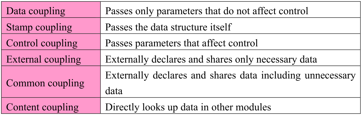
Partitioned modules are to be evaluated according to evaluation criteria, such as scope of control and scope of effect of the module, amount of partitioning of the module (the number of steps), partitioning into components, and reuse. After that, they are to be repartitioned as necessary.
p. 257 · PDF 261
[Guidelines for amount of module partitioning]
- • Partition a single component into about 10-200 modules.
- • Partition a component so that partitioned modules have a hierarchical depth of up to 4
levels. - • Partition a component so that the number of modules at the same depth (i.e., level) is
10 or less.
Module specification design (or program design) is to be performed to clarify the functions of the partitioned modules. At this time, methods for representing module specifications include flowcharts, decision tables, and NS (Nassi-Shneiderman) charts. (Details are described in “2-2-1 Structured Design.”) In “(ii) Detailed design of software interfaces” (interface design), physical design is to be performed, which includes responsiveness, hardware functions, and others along with what have been considered in architectural design. In input/output detailed design, as input media, input design to determine input data checking methods (e.g., numeric checks, limit checks, format checks, duplication checks, matching checks, balance checks, logical checks (validity checks)), output objectives, and others are considered, output media (e.g., display screens, printer forms) is determined. In addition, output design is performed to design layouts based on the limitations of paper (specialized paper, general paper), displays, printers, and others. In physical data design for files and others, data property analysis, file organization methods (e.g., sequential organization, relative organization, indexed sequential organization, partitioned organization, direct organization), recording media, the layout of records (generally with key items positioned to the front, and reserved items added with expansion taken into account), and others are determined. This way of thinking is that same as that in “(iii) Detailed design for the databases,” and a physical data model is created with an awareness of the DBMS product to be implemented. With regard to interfaces between software components and interfaces between software units, appropriate interfaces (e.g., parameters and return values) are to be defined on the basis of the relationships between modules (i.e., main routines) that perform calls and modules (i.e., subroutines) that are called. At this time, call by value and call by reference are to be used appropriately as methods for calling subroutines (i.e., methods for passing parameters). In “(v) Definition of test requirements for software units,” in the same manner as test requirements for software integration, checklists, and others are to be used. In addition, criteria are to be created for test requirements for not only black box tests but also white box tests that verify whether the internal structure (i.e., algorithm) of the software is correct. (Details of black box tests and white box tests are described in “1-2-4 Software Construction Process.”)
p. 258 · PDF 262
(2) Evaluation and review of software detailed design
The following tasks are to be executed in evaluation and review of software detailed design.
(i) Evaluation of software detailed design Software detailed design is to be evaluated, with consideration given to the criteria of traceability to the requirements of the software configuration item, external consistency with architectural design for the software configuration item, internal consistency between the software components and software units, appropriateness of design methods and standards used, feasibility of testing, and feasibility of operation and maintenance. (ii) Implementation of joint review in software detailed design
A joint review is to be conducted, with agreement obtained concerning software architectural design.
Section progress
Original chapter exercises
Original chapter exercises →New FE Textbook Vol.2 · First Edition, April 2015