Highlighted text? Practice this concept. Highlighted passages and figures open related questions.
Practice related questions (12)Progress & bookmarks
Current section
2-2-2 Object-Oriented Design
p. 286
Practice this section 12 linked exam questions with default filters
Progress
Not marked complete
Related questions in this lesson 20
Class inheritance2UML sequence diagrams2Use-case actors and services3Encapsulation1UML class multiplicity and generalization notation3UML standardized modeling across development2States and transitions in UML1Classes and instances1Polymorphic behavior2State-machine diagrams1Information hiding and simplified interfaces1Delegation1p. 286 · PDF 290
2-2-2 Object-Oriented Design
Object-oriented design is an analysis/design technique based on the concepts of object orientation. Techniques for development with a focus on data, like object-oriented design, are called DOA (Data Oriented Approach) or data-oriented design. In object-oriented design, software is partitioned into components called objects, which are combined during development. This enables higher efficiency and quality in software development.
(1) Object orientation

Source visual description
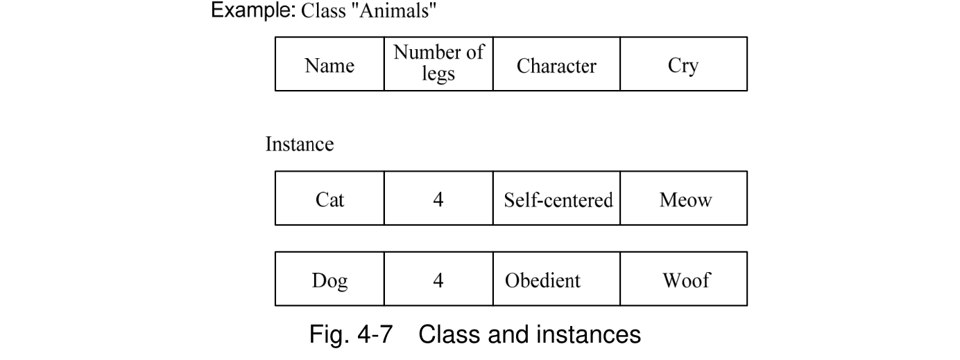
Fig. 4-7. Example: Class "Animals" has Name, Number of legs, Character and Cry columns. Under Instance, Cat has 4 legs, Self-centered character and Meow cry; Dog has 4 legs, Obedient character and Woof cry.

Source visual description
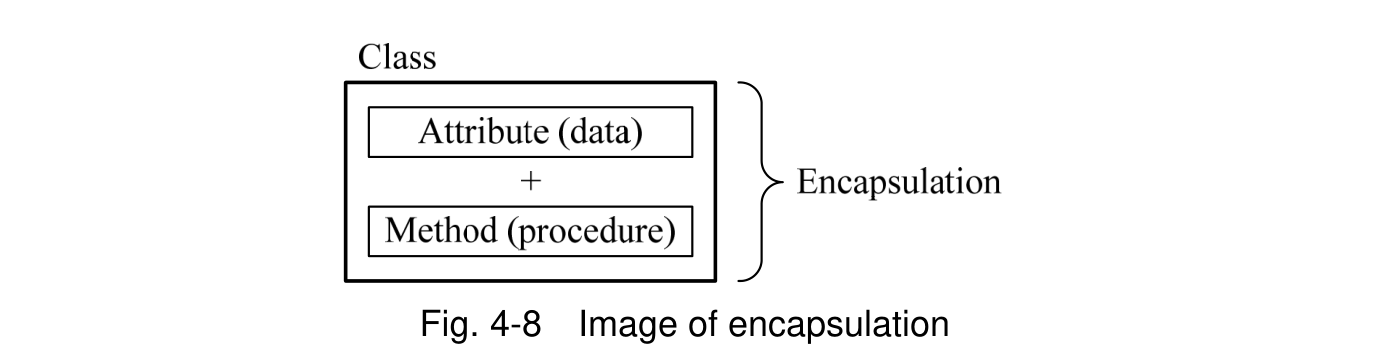
Fig. 4-8. A Class encloses Attribute (data), a plus sign, and Method (procedure). A right-side brace labels their grouping Encapsulation.
p. 287 · PDF 291
grouped and managed as packages to facilitate reuse. Also, typical object-oriented languages, such as Java, offer APIs, which are packages that group reusable classes. While classes can be used alone, associating multiple classes further enhances usability and others. Class relationships (i.e., associations) in object orientation include the following:
- • “is-a” relationship (specialization/generalization relationship)
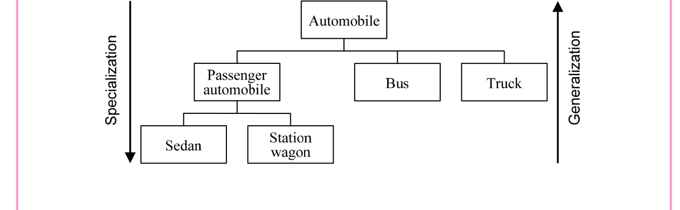
This is a relationship in which sections common to several classes are extracted to define a higher-level class. The higher-level class is called a superclass and the lower-level classes are called subclasses. Extracting the common sections from multiple subclasses is called generalization; conversely, refining a superclass is called specialization.

Source visual description
Automobile is above Passenger automobile, Bus and Truck. Passenger automobile is above Sedan and Station wagon. A downward arrow on the left is Specialization; an upward arrow on the right is Generalization.
- • “part-of” relationship (aggregation/decomposition relationship)
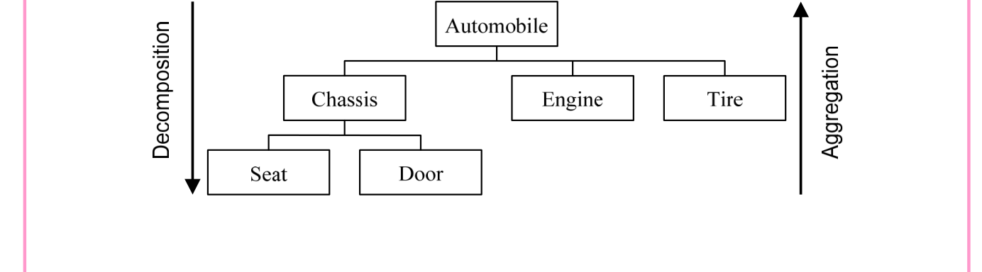
This is a relationship in which multiple lower-level classes are aggregated to compose a single higher-level class. The development of higher-level classes into lower-level classes is called decomposition, and the grouping of lower-level classes into higher-level classes is called aggregation.

Source visual description
Automobile is above Chassis, Engine and Tire. Chassis is above Seat and Door. The left downward arrow is Decomposition and the right upward arrow is Aggregation.
- • “has-a” relationship
This relationship means that a higher-level class holds a lower-level class. This relationship has almost the same meaning as the “part-of” relationship. However, they differ in that whereas the higher-level class is not possible in the “part-of” relationship
p. 288 · PDF 292
if even one lower-level class is missing, it is possible in the “has-a” relationship even if multiple lower-level classes are missing.

Source visual description
Automobile has Child seat, Drink holder and Car navigation system below it.
Characteristics of object orientation include the following:

Source visual description
The Automobile class contains Model and engine displacement and has Bus (Capacity) and Truck (Load capacity) beneath it. A rightward arrow labelled Inheritance leads to Truck containing Model, engine displacement and load capacity.
- • Differential programming
This is a programming technique in which a superclass is inherited, and only the portions differing from the superclass are defined in the subclasses. - • Polymorphism
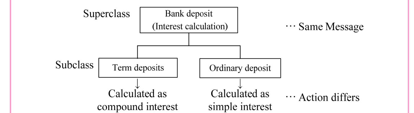
This is the ability of actions (or behaviors) for a given message to differ according to the class (i.e., object). Polymorphism is implemented by override (redefinition) etc. · 2 questions

Source visual description
Superclass Bank deposit (Interest calculation) receives Same Message. Its subclasses are Term deposits, calculated as compound interest, and Ordinary deposit, calculated as simple interest. The lower label is Action differs.
p. 289 · PDF 293
- • Propagation
This is the ability, when operations are applied to a given class (i.e., object), to automatically apply the operations to other related classes (i.e., objects). - • Role
It is possible to group multiple instances and define roles. Actions will change when roles differ, even for instances of the same class.
Class relationships are extremely important in object orientation. Since many attributes in object orientation are also determined by class relationships, classes and the relationships among classes are summarized as a class diagram. Class diagrams are diagrams included in the UML (Unified Modeling Language) described later.
(2) Object-oriented development model
Object-oriented development model is a spiral model-type development technique that begins with analysis/design/development of important classes, and proceeds in stages to analysis/design/development of detailed classes.
[Development phases in the object-orientated development model]
| Object-oriented analysis | Object-oriented design | Object-oriented programming | |
|---|---|---|---|
| Architectural design | Class design | ||




(i) OOA (Object-Oriented Analysis) This models the real world that is the target of development through object orientation (i.e., the integration of data and procedures). E-R diagrams and state transition diagrams are used in the modeling.
- • E-R diagram / ER model
These are data models that represents the targeted work as entities and relationships among entities. They are used in data modeling, and others which represents the data structures used in work.


Source visual description
Wholesaler connects by a right-pointing arrow to Product. Product connects to Customer with a line that has arrowheads at both ends.
- • One fact in one place
This is a concept in data analysis that manages one fact (i.e., information) in one place. It checks whether the same data, used in multiple tasks, is managed
p. 290 · PDF 294
under different names. In a database, one fact in one place is achieved by performing normalization. (ii) OOD (Object-Oriented Design) The architectural design (i.e., global design) that equates to external design in the waterfall model and the class design (i.e., local design) that equates to internal design are carried out. (iii) OOP (Object Oriented Programming) Object orientation is more the concept of clearly defining methods of using classes than the concept of creating programs. In this phase, class libraries (i.e., libraries for preserving created classes) and packages are referenced in order to reuse existing classes. Programming languages used include Java and C++.
- • CORBA (COmmon Request Broker Architecture)
This is a standard specification that enables message exchange among objects developed by using different programming languages in a distributed environment. - • IDL (Interface Definition Language)
This is a set of rules concerning interfaces for reusing created objects from other programming languages.
(3) UML (Unified Modeling Language)
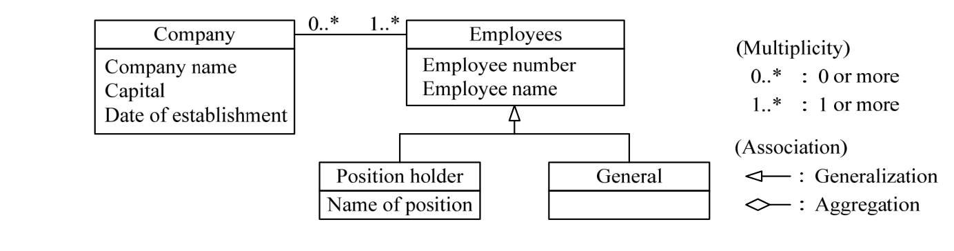
(i) Class diagram This is a diagram that represents the relationships among classes. It describes class names, operations, attributes, multiplicity, role names, and others. It is also used as data models.

Source visual description
Company contains Company name, Capital and Date of establishment; Employees contains Employee number and Employee name. Their association is labelled 0..* at the Company end and 1..* at the Employees end. Position holder (Name of position) and General join to an open triangle pointing up to Employees. The legend defines 0..* as 0 or more and 1..* as 1 or more, with open triangle Generalization and open diamond Aggregation association symbols.
p. 291 · PDF 295

Source visual description
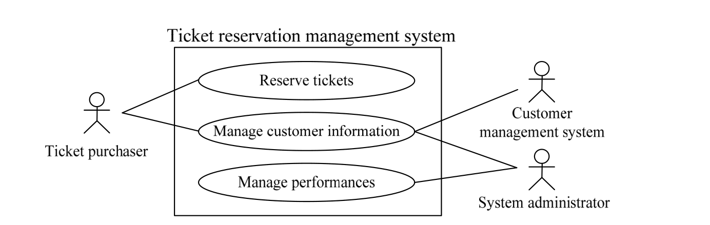
Ticket reservation management system encloses Reserve tickets, Manage customer information and Manage performances use-case ovals. Ticket purchaser at left connects to Reserve tickets and Manage customer information. Customer management system at right connects to Manage customer information. System administrator at right connects to both Manage customer information and Manage performances.

Source visual description
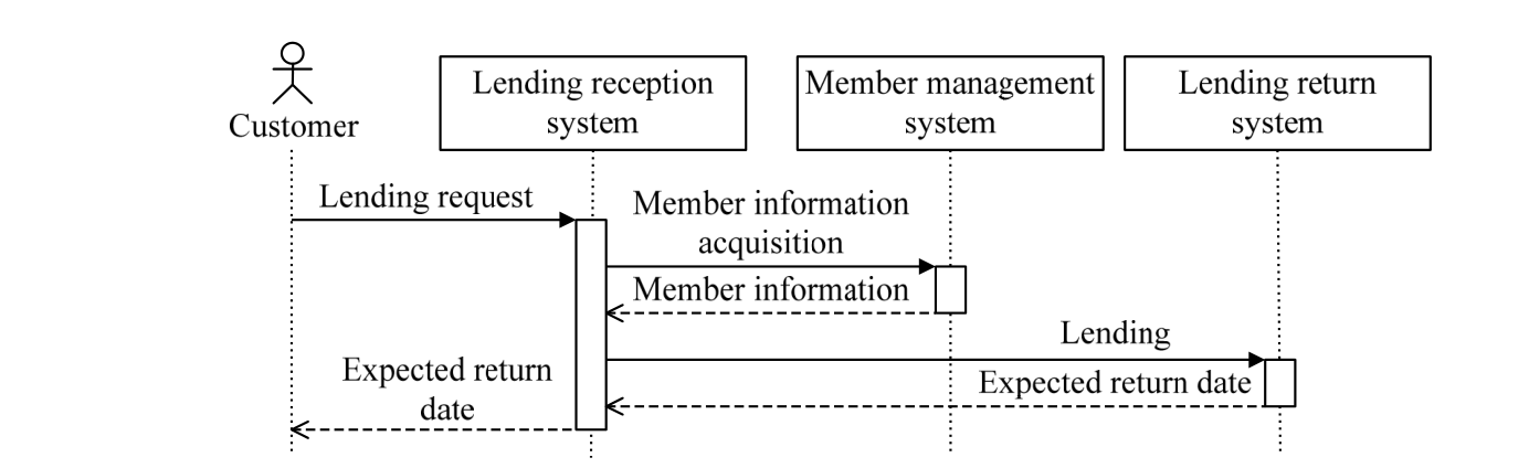
Four lifelines are Customer, Lending reception system, Member management system and Lending return system. Customer sends Lending request to Lending reception system, which sends Member information acquisition to Member management system. A dashed return carries Member information back. Lending reception system sends Lending to Lending return system; a dashed Expected return date returns to reception and then a dashed Expected return date returns to Customer. Original activation rectangles and time ordering remain intact.
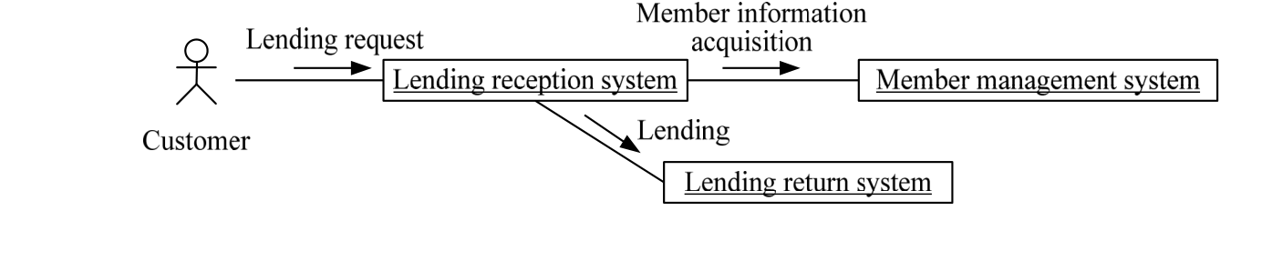
(iv) Communication diagram (collaboration diagram) This is a type of interaction diagram that represents exchange (i.e., message flow) of messages, with a focus on objects and such others.

Source visual description
Customer sends a Lending request to Lending reception system. From Lending reception system a rightward Member information acquisition arrow reaches Member management system and a downward-right Lending arrow reaches Lending return system. The system object labels are underlined in the source.
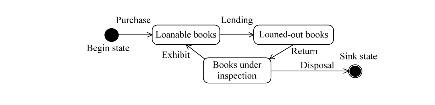
(v) State machine diagram (statechart diagram)
p. 292 · PDF 296

Source visual description
A solid Begin state leads by Purchase to Loanable books. Lending leads from Loanable books to Loaned-out books. Return leads from Loaned-out books to Books under inspection. Exhibit leads from Books under inspection back to Loanable books. Disposal leads from Books under inspection to the double-circle Sink state.
(vi) Activity diagram This is a diagram that represents the flow of systems and work.


Source visual description
A solid Initial node leads through a merge diamond to Lending processing and then to a decision diamond. The [No books] branch goes right through Notification processing to the Activity final node. The [Books are remaining] branch loops back from the decision to the merge before Lending processing.
(vii) Component diagram This is a diagram that represents the configuration of systems and software. In general this is a diagram that depicts software component configuration, and on the other hand, a diagram that depicts system hardware configuration is called a deployment diagram. (viii) Object diagram This is a diagram that represents the relationships among objects (i.e., instances). (ix) Package diagram This is a diagram that represents the associations among packages of grouped classes. (x) Timing diagram This is a diagram that represents message exchanges and the status of object lifelines that change over time.
[Other languages]
- • ADL (Architecture Description Language)
This is a language that describes the architecture (i.e., structure) of systems (i.e., software). UML can be considered a type of ADL. - • DDL (Data Definition Language)
This is a language that defines the logical structure and names of databases.
Section progress
Original chapter exercises
Original chapter exercises →New FE Textbook Vol.2 · First Edition, April 2015